Part 3: Multiplication and Division
So we've figured out addition and subtraction. Multiplication, then, doesn't actually seem so bad; indeed, it is only repeated addition...
Multiplication
So now we turn to multiplication. Let's think about how we might multiply two numbers in base ten. The standard method is to do something like this:
	   471
	× 1011
	------
	   471
	  471
	 000
	471
	------
	  1     (carry from 4+7)
	475181
	------
	476181
You might have noticed that I deliberately chose to make the second number only have the digits 0 and 1. This is a very useful feature of binary: since the bits can only ever be 0 or 1, at each step, we either add the number as is or we don't. (In contrast, with base ten we might have to add some multiple of 471.)
For now, we're also going to ignore overflow entirely, and just assume that we can somehow output twice as many bits. We'll also be using unsigned integers, so 1001 means 8+1 = 9, not -7. (Signed multiplication is a little trickier. However, if you don't care about overflow and want a 4-bit output, you can actually multiply the two's complement representations directly, as if they were positive numbers! Try it yourself below if you want.)
Before we get started, I want to let you know that this page only has one exploration where you actually have to make the circuit work. However, I still urge you to at least play around with each one so you get a sense of what it's doing. With that said, let's jump right to a naive attempt at building a circuit:
Actually, the top right adder isn't really necessary, although it could be helpful if you wanted to have a multiply-add operation that computes (A * B) + C given three inputs.
But that gets a bit unwieldy if you try to imagine 32 or 64 of them. In fact, that would be extremely slow. Although it all looks instantaneous here, each of those wires is distance that electrons have to move at some finite speed.
Even the "add" operation itself is fairly slow for a 32-bit machine; a signal has to travel through 32 full adders to make the final answer. (There are no shortcuts: imagine something like 7 + 3999994. You can't find out the millions digit until you finish adding the right six digits.) Multiplication would then require waiting for 32 of those add cycles.
There are actually more complicated multiplier designs that cut down on this time considerably, by using something called a "carry save adder". These designs are quite complicated, but the basic idea is similar to how I did the multiplication: I wrote (well, typed) all the 471's, then added each column and carried as needed.
But the reason this works is that multiplication is just repeated addition. All the information you need is right there in plain sight to begin with. Unfortunately, this is not true of division, which means we're going to need more complicated steps to make that work.
Division...
Is it just me, or does division feel harder than multiplication? Here's an example of some long division, side-by-side with the multiplication from before.
        1011
471 | 476223
      471
      ---
       05223
       000
       -----
        5223
        471
        ----
         513
         471
         ---
          42
   471
× 1011
------
   471
  471
 000
471
------
  1
475181
------
476181
One thing you may have noticed is that division took more steps. There is no column-by-column trick to make the subtraction faster. What's worse, we have to make a decision at each step, of whether or not to subtract 471 (actually, in base ten there are ten possible subtractions including zero). There's no good way to predict, say, whether the last step will need a subtraction or not without calculating it all the way down to 513. (Actually, people have come up with complicated ways to predict divisions, but that's way beyond our scope here.)
This is going to involve a much different kind of circuit from the static ones we've seen so far. Our circuit is going to need a lot more time, and a bunch of new components. Since this is going to be a lot of content, I've decided to first build a slow multiplier that will feature a lot of the components we need to build a divider. You'll notice that the divider ends up being very similar. But before we get to any of that, let's start with three new components...
Making Decisions
Remember how I said that with division, we need to be able to choose between two different options? How would you go about doing that?
I mean, a bit is already in some sense a "choice" between ON or OFF. But what if you need to choose between, say, two 32-bit numbers? Or what about more than two, even?
Actually, for the purposes of multiplication and division, we will only need to choose between two options, so let's figure that out. The simplest case, of course, is choosing between two bits. This isn't very complicated, but there are some subtleties to understand.
The gate we're going to build is called a "multiplexor" (not a multiplier!) or a "selector" (although I personally like the name "choice gate"). It takes three inputs: the selection input S, and two others which I'll call A and B. The output is determined as follows:
- If S is ON, then we output whatever A is.
- If S is OFF, then we output whatever B is.
The circuit for this is not that complicated; you only need 3-5 gates (I'm not telling you how many NOTs to use!). But it's a little tricky to get this one right. I've started you off with a hint (namely, how I arranged the wires). It's your job to figure out which gates to use.
Choice Exploration
Tick, tock, tick, tock...
In computer hardware, one of the fundamental concepts is the clock. This is a signal that alternates up-down-up-down-up-down-... for as long as the computer has power. This is how it knows when, for instance, it is time to run the next instruction safely (any operations are required to take less time than one cycle of the clock, or else the program has to wait). We'll also use it for our divider (in a real circuit, keeping the time synchronized helps prevent gates from giving the wrong values, if for instance two signals arrived at different times).
Here, I'm representing this with the left output being the "up" phase and the right output being the "down" phase of the clock. It also has an input bit, which I use more as a "start button" in the multiplier and divider circuits to activate the clock (you could think of it as the power source).
Because it's common for operations to happen on both the rising and falling edges of the clock, I've represented it here with two output bits; at any given time only one of them is on. You can think of the right one as having a built-in NOT gate.
This exploration isn't very interesting in and of itself, but it does have a new feature: the speed control. You might find it useful to slowly work your way through the more complicated circuits.
Clock Exploration
- There are three buttons on the right: Pause, Play, and Step. (With bigger explorations and smaller screens, the buttons might end up being below the exploration.)
- Clicking Play will cause the exploration to periodically update; in this case, the clock will cycle back and forth. The slider controls the speed.
- Clicking Step will cause it to advance once. You'll want to pause it first if you want to step it at your own pace.
- The green input bit at the top activates the clock component; turning it off disables the clock. (It's part of the circuit, so it operates independently of the Pause/Play buttons. If everything is red, clicking Play and Step won't do anything.)
With a clock we can make a simple counter that adds 1 every clock cycle. Actually, for our purposes later I'll use this design. When the power is off, it resets to its default value (here 5); when the power comes on, it counts down every clock cycle.
Sorry, at this moment I don't have a full circuit showing how to build this. It's coming soon though! For now, I'll just say that it's not difficult to build with just a subtractor and some registers. In fact, it might be fairly obvious once you see the multiplier.
Registers
We also need some more persistent components, something that can "remember" what it had before. That looks difficult, but we can actually implement it fairly easily with a simple trick: we take the output and wire it back into the input!
"Registers" are just a fancy name for a group of bits that stores information. A 32-bit register, for instance, can hold any 32 bits you want for as long as you need them (if the power stays on).
The design I am going to use is non-informatively called a "D latch". There are two inputs: a "load" input and a "data" input. If the former is ON, the register adopts the value of the "data" input; if the "load" is OFF, the register remembers what it had before.
This process might remind you of something. Indeed, we can simulate this by simply wiring a choice gate back on itself.
Register Exploration
In practice, however, registers are usually implemented with more complicated circuitry that responds to the clock. This is because in real life, signals take time to move through wires. Allowing registers to change only when the clock ticks can prevent data from being corrupted. This is all getting very advanced, though, so we'll use the unclocked version of the register for now.
Multiplication, the Slow Way
With all of those components, it is time to do our multiplication!
What we're going to do this time is to start with a blank "canvas" of bits. It's easier to keep the adder in one place and move bit values, so we add into the upper 6 bits (the final answer may be as large as 12 bits) and then shift the register downward. (By "shift", I mean to shift the values of the bits. So in a shift cycle, each bit inherits the value of its left neighbor.) In decimal, it looks like this:
	Register:  000000    [1011]
	Add:       471000    [1011]
	Shift:     047100    [ 101]
	Add:       518100    [ 101]
	Shift:     051810    [  10]
	Don't add: 051810    [  10] (don't add because of the 0)
	Shift:     005181    [   1]
	Add:       476181    [   1]
To implement this in hardware, we need to keep track of which bit in the second number we are on. The easiest way to do this is with a second register of size 6. It gets shifted when the large one does, and we just tell the adder to keep the original value of the register if that bit is 0. (Notice the "Don't add" step above because the hundreds digit was a zero.)
There's a lot going on here, but don't panic! A detailed explanation follows, but see if you can figure out what's going on by watching it. Remember, this isn't what multiplication usually looks like; it's just here to compare with division.
Exploration Instructions
Heads up! Unlike the previous simulations that calculated immediately, multiplication and division take time. To operate this version:
- Dark Red = 0 and Light Green = 1.
- Click the circles in the upper left to make the first number. (You have to make the number in binary. The display number can NOT be typed into.)
- Click on the row of circles in the upper mid-right to make the second number.
- When you are ready, click the large red button in the upper right corner to turn the machine "on". (Note that the "Play" button enables animation but won't actually start the calculation unless the big red bit is made green.)
- Too fast? There is speed control to the right of (or below) the exploration. Click "pause" to pause the circuit and "step" to do one iteration at a time. You can also adjust the animation speed.
For best results, try setting the second input to something with several 1 bits and several 0 bits. A good number for this is 110011 (51).
Multiplication: What Just Happened?
All right, so maybe all that wiring confused you a little. Let's go through it piece by piece. You probably noticed there were two alternating actions, which I will call "add" and "shift". "Shift" moves a bunch of values and "add" helps the product grow. In more detail:
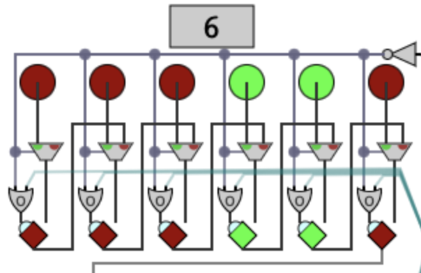
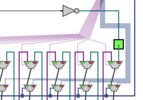
This portion of the circuit, surrounding the second input, copies that input into a register. The wires coming from the upper right come from a NOT gate on the start button. If the start button is off, that not gate is on, so the selectors will choose the input bits, effectively resetting this register. Otherwise, they will select the value of the previous bit, thus trying to shift the register.
However, the "write" signal is connected to an OR gate. The "write" is active when the teal wires are on OR the start button is off. Teal is the "shift" signal, and the start button being off is a reset. So in shift phase, the values all move one place right, but in add phase, this register stays put. The value of the LSB (least significant bit) doesn't go anywhere in shift phase, but it does have another purpose...
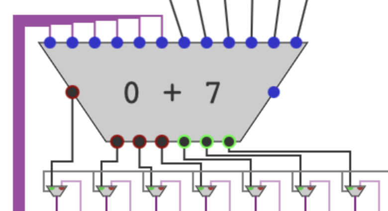
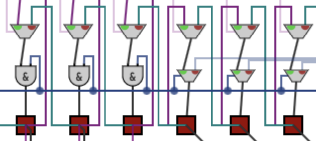
...and for that, we come to the adder. Its purpose is to add the first input to the upper 6 bits of the product register. The selector decides whether to use this sum (if the LSB from above is 1) or keep the state as is (if 0). The faded purple wire is connected to the product register, while the solid purple wire comes down to more selectors. (This screenshot was edited to remove the clutter from the second input circuitry.)
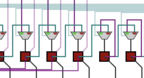
Those selectors then control what happens to the product register. (It doesn't look like a register because the bits are always moving, on both phases of the clock. But the choice gate wiring them to themselves has the same register-like functionality.) The faded teal wires are the control signal for shifting (just like above). When those are active, all the bit values slide one place to the right. Otherwise, the bits on the right hold their own state, while those on the left receive the value from the selector above (which might or might not be the addition result).
Of course, now we just made a value that has twice as many bits as the computer. If your computer is 64-bit, then the multiplication can theoretically use as many as 128 bits. (Challenge: Find a multiplication in the above where the 12th bit from the right is a 1.) One approach, used by the MIPS architecture, is to store the result in a special "high" and "low" register. Then, programs can use an instruction called mfhi and mflo ("move from high/low") to extract the two halves separately. Usually only the lower half is actually used; the upper half would only check if there is overflow.
Division
Long division is also rather tricky. Let's take the example from earlier with a slight modification:
        1011
471 | 476223
      471
      ---
       05223
       000
       -----
        5223
        471
        ----
         513
         471
         ---
          42
Many things are similar to multiplication, actually. If you remember the multiplication hardware, we started with an empty register, and added to the left half and then shifted all the bits to the right. Here, we do the opposite: the register now starts with the numerator, and we repeatedly subtract and shift left.
When the subtractor gets its result, we first check the carry-out bit and see if it is 0. (If it were 1, then we got a negative result.) This is sent into choice gates to decide whether or not to use the subtraction.
Now, a naive implementation of the hardware would just have a second register for storing the quotient. However, because of the way we shift the register upward, we can actually just use the lower half of the register to hold the quotient.
Why is this? Well, when done this way, we can now use the same hardware for multiplication and division! The mfhi instruction would now mean "extract the remainder", and mflo now gets the quotient.
There's one other complication, though. Remember that with multiplication, we started with a blank canvas and added on to it. With division, unfortunately, we have to start with the numerator in the big register. This requires a few extra selector gates, but it isn't that bad; here, we just use the power button as the selector.
Like before, I made the power button shut itself off when the computation is done. Notice how it immediately resets the big row now. The top number is the numerator and the bottom number is the denominator.
Because the circuit is more complicated, I've decided to make it use 5 bits instead of 6. The range of the inputs and outputs are therefore 0 to 31.
Here's a few things to try:
- Try some stress tests: 31 divided by 1, 31 divided by 31, 1 divided by 31, 1 divided by 1, 0 divided by 1 or 31.
- What happens if you divide by zero? See if you can guess, then try it. (A real computer would issue some kind of error if you tried to do so, but that requires more work.)
- Another good thing to try is dividing something with a large remainder, say, 11 by 12 (or 22 by 12) and then comparing it to 13 (or 26) by 12.
Division: What Just Happened?
As I said, it's very similar to the multiplier circuit. However, there are several important differences.
Well, there we have it! We've successfully worked our way through all of the basic arithmetic operations. I have a separate page that has just the multiplication and division circuits (with instructions) if you'd like to use this in teaching.
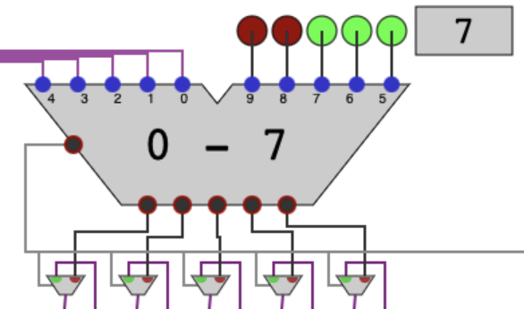
Here, the subtraction selector gates are choosing with the carry bit itself, instead of the other input. This is how we make the decision of whether or not to subtract: because of 2's complement, a negative result will involve the carry bit (the result is technically 6 bits, not 5) being on. If that happens, we just hold the register as is.
The subtractor's carry also determines whether we insert 0 or 1 into the register. The subtraction went through when the carry is 0, but that's when we need to write a 1. So we use a NOT gate to flip it before doing the insertion.
The last difference is that we don't start with a blank register. The pale blue wires are coming from the input way up top; the darker blue ones are from the power button. When the power is on, we use the top choice gate almost like we did in multiplication except that we shift left instead.
However, when the "power" (really the control switch) is off, we initialize the register. On the left, those bits need to be cleared (zeroed) when the control is off, so we just use AND gates because (0 AND anything) is 0. On the right, we feed that through a choice gate so that we capture the input (while still keeping the shift functionality when the control switch is on).
You Did It!
Congratulations! You now understand how to do the five basic operations in computer hardware! I say five, because in basically every programming language ever, the quotient and remainder operations are separate. For instance, in C and Java, 20 / 3 gives the quotient 6, while 20 % 3 gives the remainder 2.
Or maybe some things are still a little confusing. That's okay. You can continue to play with the explorations. If you have suggestions or bugs to report, you can email me at thelast19digitsofpi <at> gmail <dοt> com.
Finally, I have the muliplier and divider explorations together on their own page, for ease of use in lectures. There are instructions but no detailed explanations.
Thank you for learning about this, and have a good day!